THE STRAIN GAUGE
The strain gauge has been in use for many years and is the fundamental sensing element for many types of sensors, including pressure sensors, load cells, torque sensors, position sensors, etc.
The majority of strain gauges are foil types, available in a wide choice of shapes and sizes to suit a variety of applications. They consist of a pattern of resistive foil which is mounted on a backing material. They operate on the principle that as the foil is subjected to stress, the resistance of the foil changes in a defined way.
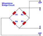
The strain gauge is connected into a Wheatstone Bridge circuit with a combination of four active gauges (full bridge), two gauges (half bridge),
or, less commonly, a single gauge (quarter bridge). In the half and quarter circuits, the bridge is completed with precision resistors.
The complete Wheatstone Bridge is excited with a stabilised DC supply and with additional conditioning electronics, can be zeroed at the null point of measurement. As stress is applied to the bonded strain gauge, a resistive changes takes place and unbalances the Wheatstone Bridge.
This results in a signal output, related to the stress value. As the signal value is small, (typically a few millivolts) the signal conditioning electronics provides amplification to increase the signal level to 5 to 10 volts, a suitable level for application to external data collection systems such as recorders or PC Data Acquistion and Analysis Systems.
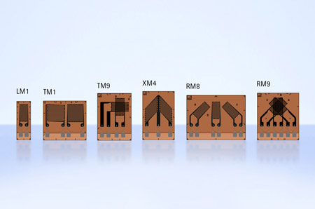
Some of the many Gauge Patterns available
Most manufacturers of strain gauges offer extensive ranges of differing
patterns to suit a wide variety of applications in research and industrial
projects.
They also supply all the necessary accessories including preparation materials, bonding adhesives, connections tags, cable, etc. The bonding
of strain gauges is a skill and training courses are offered by some suppliers.
There are also companies which offer bonding and calibration services,
either as an in-house or on-site service.
More about the Strain Gauge...
If a strip of conductive metal is stretched, it will become skinnier and longer, both changes resulting in an increase of electrical resistance end-to-end. Conversely, if a strip of conductive metal is placed under compressive force (without buckling), it will broaden and shorten. If these stresses are kept within the elastic limit of the metal strip (so that the strip does not permanently deform), the strip can be used as a measuring element for physical force, the amount of applied force inferred from measuring its resistance.Such a device is called a strain gauge. Strain gauges are frequently used
in mechanical engineering research and development to measure the stresses generated by machinery. Aircraft component testing is one area of application, tiny strain-gauge strips glued to structural members, linkages, and any other critical component of an airframe to measure stress. Most strain gauges are smaller than a postage stamp, and they look something like this:
A strain gauge's conductors are very thin: if made of round wire, about
1/1000 inch in diameter. Alternatively, strain gauge conductors may be
thin strips of metallic film deposited on a nonconducting substrate material called the carrier. The latter form of strain gauge is represented in the previous illustration. The name "bonded gauge" is given to strain gauges that are glued to a larger structure under stress (called the test specimen) The task of bonding strain gauges to test specimens may appear to be very simple, but it is not. "Gauging" is a craft in its own right, absolutely essential for obtaining accurate, stable strain measurements. It is also possible to use an unmounted gauge wire stretched between two mechanical points to measure tension, but this technique has its limitations.Typical strain gauge resistances range from 30 Ohms to 3 kOhms (unstressed). This resistance may change only a fraction of a percent
for the full force range of the gauge, given the limitations imposed by
the elastic limits of the gauge material and of the test specimen. Forces
great enough to induce greater resistance changes would permanently
deform the test specimen and/or the gauge conductors themselves, thus
ruining the gauge as a measurement device. Thus, in order to use the
train gauge as a practical instrument, we must measure extremely small
changes in resistance with high accuracy.Such demanding precision calls for a bridge measurement circuit. Unlike
the Wheatstone bridge shown in the last chapter using a null-balance
detector and a human operator to maintain a state of balance, a strain
gauge bridge circuit indicates measured strain by the degree of imbalance, and uses a precision voltmeter in the center of the bridge to provide an accurate measurement of that imbalance:
Typically, the rheostat arm of the bridge (R2 in the diagram) is set at a value equal to the strain gauge resistance with no force applied. The two ratio arms of the bridge (R1 and R3) are set equal to each other. Thus, with no force applied to the strain gauge, the bridge will be symmetrically balanced and the voltmeter will indicate zero volts, representing zero force on the strain gauge. As the strain gauge is either compressed or tensed, its resistance will decrease or increase, respectively, thus unbalancing the bridge and producing an indication at the voltmeter. This arrangement, with a single element of the bridge changing resistance in response to the measured variable (mechanical force), is known as a quarter-bridge circuit.
As the distance between the strain gauge and the three other resistances in the bridge circuit may be substantial, wire resistance has a significant impact on the operation of the circuit. To illustrate the effects of wire resistance, I'll show the same schematic diagram, but add two resistor symbols in series with the strain gauge to represent the wires:
The strain gauge's resistance (Rgauge) is not the only resistance being
measured: the wire resistances Rwire1 and Rwire2, being in series with
Rgauge, also contribute to the resistance of the lower half of the rheostat arm of the bridge, and consequently contribute to the voltmeter's indication. This, of course, will be falsely interpreted by the meter as physical strain on the gauge.While this effect cannot be completely eliminated in this configuration, it can be minimized with the addition of a third wire, connecting the right side of the voltmeter directly to the upper wire of the strain gauge:
Because the third wire carries practically no current (due to the voltmeter's extremely high internal resistance), its resistance will not drop any substantial amount of voltage. Notice how the resistance of the top wire (Rwire1) has been "bypassed" now that the voltmeter connects directly to the top terminal of the strain gauge, leaving only the lower wire's resistance (Rwire2) to contribute any stray resistance in series with the gauge. Not a perfect solution, of course, but twice as good as the last circuit!
There is a way, however, to reduce wire resistance error far beyond the method just described, and also help mitigate another kind of measurement error due to temperature. An unfortunate characteristic of strain gauges is that of resistance change with changes in temperature. This is a property common to all conductors, some more than others. Thus, our quarter-bridge circuit as shown (either with two or with three wires connecting the gauge to the bridge) works as a thermometer just as well as it does a strain indicator.
If all we want to do is measure strain, this is not good. We can transcend this problem, however, by using a "dummy" strain gauge in place of R2, so that both elements of the rheostat arm will change resistance in the same proportion when temperature changes, thus canceling the effects of temperature change:
Resistors R1 and R3 are of equal resistance value, and the strain gauges are identical to one another. With no applied force, the bridge should be in a perfectly balanced condition and the voltmeter should register 0 volts. Both gauges are bonded to the same test specimen, but only one is placed in a position and orientation so as to be exposed to physical strain (the active gauge). The other gauge is isolated from all mechanical stress, and acts merely as a temperature compensation device (the "dummy" gauge).
If the temperature changes, both gauge resistances will change by the same percentage, and the bridge's state of balance will remain unaffected. Only a
differential resistance (difference of resistance between the two strain
gauges) produced by physical force on the test specimen can alter the
balance of the bridge.
Wire resistance doesn't impact the accuracy of the circuit as much as before, because the wires connecting both strain gauges to the bridge are approximately equal length. Therefore, the upper and lower sections of the bridge's rheostat arm contain approximately the same amount of stray resistance, and their effects tend to cancel:
Even though there are now two strain gauges in the bridge circuit, only one is responsive to mechanical strain, and thus we would still refer to this arrangement as a quarter-bridge. However, if we were to take the upper strain gauge and position it so that it is exposed to the opposite force as the lower gauge (i.e. when the upper gauge is compressed, the lower gauge will be stretched, and visa-versa), we will have both gauges responding to strain, and the bridge will be more responsive to applied force. This utilization is known as a half-bridge. Since both strain gauges will either increase or decrease resistance by the same proportion in response to changes in temperature, the effects of temperature change remain canceled and the circuit will suffer minimal temperature-induced
measurement error:
An example of how a pair of strain gauges may be bonded to a test specimen so as to yield this effect is illustrated here:
With no force applied to the test specimen, both strain gauges have equal resistance and the bridge circuit is balanced. However, when a downward force is applied to the free end of the specimen, it will bend downward, stretching gauge #1 and compressing gauge #2 at the same time:
In applications where such complementary pairs of strain gauges can be bonded to the test specimen, it may be advantageous to make all four elements of the bridge "active" for even greater sensitivity.
This is called a full-bridge circuit:
Both half-bridge and full-bridge configurations grant greater sensitivity over the quarter-bridge circuit, but often it is not possible to bond complementary pairs of strain gauges to the test specimen. Thus, the quarter-bridge circuit is frequently used in strain measurement systems.
When possible, the full-bridge configuration is the best to use. This is true not only because it is more sensitive than the others, but because it is linear while the others are not. Quarter-bridge and half-bridge circuits provide an output (imbalance) signal that is only approximately proportional to applied strain gauge force.
Linearity, or proportionality, of these bridge circuits is best when the amount of resistance change due to applied force is very small compared to the nominal resistance of the gauge(s). With a full-bridge, however, the output voltage is directly proportional to applied force, with no approximation (provided that the change in resistance caused by the applied force is equal for all four strain gauges!).
Unlike the Wheatstone and Kelvin bridges, which provide measurement at a condition of perfect balance and therefore function irrespective of source voltage, the amount of source (or "excitation") voltage matters in an unbalanced bridge like this. Therefore, strain gauge bridges are rated in millivolts of imbalance produced per volt of excitation, per unit measure of force. A typical example for a strain gauge of the type used for measuring force in industrial environments is 15 mV/V at 1000 pounds. That is, at exactly 1000 pounds applied force (either compressive or tensile), the
bridge will be unbalanced by 15 millivolts for every volt of excitation voltage. Again, such a figure is precise if the bridge circuit is full-active (four active strain gauges, one in each arm of the bridge), but only approximate for half-bridge and quarter -bridge arrangements.Strain gauges may be purchased as complete units, with both strain gauge elements and bridge resistors in one housing, sealed and encapsulated for protection from the elements, and equipped with mechanical fastening points for attachment to a machine or structure. Such a package is typically called a load cell.
This article is from 'All about circuits'...click here to visit.
How to bond a Strain gauge
The installation of a strain gauge is probably the most crucial part of strain measurement....
A poor quality installation could discredit your tests costing time and money. Bonding strain gauges requires skill, attention to detail and patience as well as the correct tools and adhesives. To check out how to do it take a look at this video...
For 'Basic Strain Measurements' article, click here...
For details of STRAIN GAUGE Suppliers, click here
sensorland.com was launched in June 2000 as a online information centre to provide engineers with technical knowledge and where to source all types of sensors and transducers including pressure sensors, load cells, vibration sensors, position sensors, humidity sensors, angle sensors, torque sensors, etc. together with the associated sensor systems for measurement and control.
Home - Search - Suppliers - Links - New Products - Catalogues - Magazines
Problem Page - Applications - How they work - Tech Tips - Training - Events -