LOAD / FORCE CELLS

The load or force cell takes many forms to accommodate the variety of uses throughout research and industrial applications. The majority of today's designs use strain gauges as the sensing element, whether foil or semiconductor.
Foil gauges offer the largest choice of different types and in consequence tend to be the most used in load cell designs. Strain gauge patterns offer measurement of tension, compression and shear forces.
Semiconductor strain gauges come in a smaller range of patterns but offer the advantages of being extremely small and have large gauge factors, resulting in much larger outputs for the same given stress. Due to these properties, they tend to be used for the miniature load cell designs.
Proving rings are used for load measurement, using a calibrated metal ring, the movement of which is measured with a precision displacement transducer.
A vast number of load cell types have developed over the years, the first designs simply using a strain gauge to measure the direct stress which is introduced into a metal element when it is subjected to a tensile or compressive force. A bending beam type design uses strain gauges to monitor the stress in the sensing element when subjected to a bending force.
More recently the measurement of shear stress has been adopted as a more efficient method of load determination as it is less dependent on the way and direction in which the force is applied to the load cell.
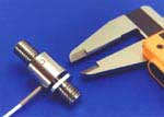
The 'S' or 'Z' Beam Load Cell

A simple design load cell where the structure is shaped as a 'S' or 'Z' and strain gauges are bonded to the central sensing area in the form of a full Wheatstone bridge.
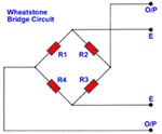
The Wheatstone Bridge Circuit
E = Excitation Voltage(typically 10 Vdc.)
O/P = Output SignalThe Bending Beam Load Cell
The strain gauges are bonded on the flat upper and lower sections of the load cell at points of maximum strain. This load cell type is used for low capacities and performs with good linearity. Its disadvantage is that it must be loaded correctly to obtain consistant results.
The Shear Beam Load Cell

The strain gauges are bonded to a reduced part of the cross section of the beam in order to maximise the shear effect. They are bonded at 45 degree angles on either side of the beam to measure the shear strains.
Used for medium to large capacities, the load cell has good linearity and is not so susceptible to extraneous loading, in particular to side loads.
Miniature Load Cells
Miniature load cells because of their compact size usually use semiconductor strain gauges as the sensing element. They are available in many different configurations for both tension and compression force measurement. They offer good performance with high outputs and high overload capabilty for protection.
Speciality Automotive/Autosport Load Cells
Many more Load Cell designs exist and we will bring you details
of these at a later stage.
LOAD CELL SPRING MEMBER DESIGN CONSIDERATIONS
Bending: Simple
FIGURE 1. Bending: The simple cantilever
Bending elements are low-force, generally less than 1,000 lbf range,
high-deflection structures offering convenient and flat strain gauging surfaces where complete push/pull strain symmetry is maintained.
Two strain gauges may be mounted on the top surface of the beam with two strain gauges mounted on the bottom of the beam in equal and opposite strain fields. Since strain gauges are directly opposite one another and beam thickness tends to be small, little likelihood exists that the strain gauges will operate at different temperatures providing generally good thermal performance. Although the cantilever beam structure provides excellent electrical nonlinearity, due to electrical symmetry, the point of load contact with the beam translates curvilinearly, producing mechanical nonlinearities.
The maximum moment resisting movement of the beam occurs at the rigid clamp with the maximum stress occurring according to My/IE where M= moment at the clamp, y = displacement from the centerline of the beam (neutral axis), 1= area moment of Inertia and E = Young's Modulus for the material used. Since the majority of the beam length serves only to increase the moment at the rigid clamp, various modifications of the simple beam are used to reduce the beam mass in the interest of maintaining a high natural frequency or to concentrate the strain at the strain gauge locations as shown in Figure 2.
Lastly, a review of beam bending characteristics of reveals that the surface strain present in the beam surface linearly varies from the point of force application to the clamp. This implies that the strain gauges will experience a strain gradient and provide an output equating to the average strain.
Constant stress beam sections can be fabricated by tapering the edges of the beam such that the tapered edges projected intersect at the point of load application to the beam as shown in top view Figure 2. In the end analysis, the load cell designer must weigh the performance benefits produced against the cost of incorporating the mechanical features shown.
FIGURE 2. Simple Cantilever EnhancementsBending: Multiple
Multiple cantilever structures produce a "multiple bending" where tension and compression strain fields exist on the same surface of the beam as shown in Figure 3a. The advantage of multiple bending elements is realized when one considers that the point of load application to the structure translates linearly along the loading axis, thereby reducing or eliminating first order onlinearities.
When the peripheral support clamp is rigid and immobile, deflection of the bending beams also produces median plane tensile loads in the beam resulting in nonlinear outputs. When the peripheral clamp is rigid and mobile, as shown in Figure 1, median plane tensile stresses are eliminated however, as the beams deflect, the moment arm reduces in length yielding yet another non-linear term and doubling the deflection of the load cell. Note that "T" is used in the Figure to denote tensile strains and "C" is used to denote compressive strain.
FIGURE 3. Multiple Bending:
Multiple bending can be implemented as shown in Figure 4 where the
sensitivity of the load cell to off-axis loads is minimized. Coupled dual-beam load cell configurations conveniently produce equal and opposite axial loads within each of the beams in response to extraneous couples. Since the strain gauges can be wired to cancel the effects of axial loads, the result is a load cell structure largely insensitive to the point of load application and articularly well-suited to commercial weighing applications. As the beams deflect, however, small changes in the moment arm lengths result producing geometric nonlinearities.Additionally, axial forces produce nonlinearities in each beam which tend to be equal and opposing, thus canceling each other. Although strain gauging inside a drilled hole is more labor intensive, the design lends itself to effective sealing. Often vacuum degassed silicone gel materials are used to fill the interior strain gaged cavity waterproofing by the "exclusion" principle.
The "binocular" dual beam design of Figure 4b is popular for low force commercial weighing applications. The thickened sections resist bending thereby reducing the compliance of the design and maximizing the natural frequency. Note that the maximum strain occurs at the transduction zones and is less than this value everywhere else within the structure. Low-profile bending-based load cells are usually configured as strain gaged diaphragms or multiple strain-gaged spoke assemblies.
Often, low profile multiple-bending designs possess four spokes at 90 degree intervals where strain gauges are wired to cancel off-axis moment-induced strains. It should be noted; when in the process of designing any load cell structure, the designer must consider all bending as well as shear loads that the spring element must communicate.
FIGURE 4. Coupled Dual-Beam Cantilevers:Many of the designs shown are depicted herein possessing right-angled corners. To minimize stress concentrations that will occur at geometric discontinuities, it is highly recommended that generous fillets be used with particular attention to possible discontinuities at surfaces tangent to radiused features. Stress risers will often show local stresses in excess of the microyield strength of the material used, producing zero instabilities and potential fatigue failures.
Forty years ago sensor designers found that performance was almost always enhanced when the sensor was fabricated from a solid billet of material and attention paid to the elimination of structural discontinuities. Today we have a much more refined understanding of materials and material behavior along with the terminology to express these various attributes and characteristics.
Bending: Ring
The bending ring shown in Figure 5 has a rich history and is popularly known as the Morehouse proving ring. The original design having been appropriated from Russia. The Morehouse proving ring was and continues to be used as a transfer standard in both sensor calibration systems and materials test systems. It is obvious from the design of the ring that each leg of the ring must communicate axial loads while simultaneously experiencing bending. The fact that both axial and bending occur within the transduction zone of the sensor characterizes ring-style load cells.
The beauty of the proving ring with strain gauges installed as shown is the fact that all gauges of the wheatstone bridge ideally experience identical axial strain, resulting in cancellation of axial strain effects in the output of the bridge. Another attribute of the ring structure relates to the smoothly varying tensile and compressive moment-induced strains that result due to loading of the cell.
The original transduction method used with the structural ring design predates strain gauges entirely where a manually "plucked" metal reed and micrometer assembly were used to detect exceptionally small deflections of the ring. A hardened ball bearing acts as the micrometer-adjustable target surface against which the reed tip oscillates, where the reed is also provided with a hardened cylindrical tip, the micrometer is adjusted to move the target until the reed just contacts the target, dampening the reed response. The displacement sensitivity of this very mechanical system is impressive. The output of the sensor is viewed directly on the micrometer scale.
It should be noted that the design of the bosses communicating load into the ring structure significantly affects the performance of the ring. The optimum proportions and dimensions of these bosses is as much determined by experience and test as it is by rigorous mechanical design.
Bosses are often undercut or modified to be made more flexible in the interest of rejecting off-axis loads trading off performance for off-axis load rejection. Likewise, transduction zones are provided with stress- concentrating notches to enhance output, natural frequency and to reduce compliance. In some cases, the extent to which these boss and flexure modifications extend are so radical as to almost defy characterization as a ring-based load cell. The single common thread in all of these designs is the fact that transduction zones must communicate both bending and axial loads.
FIGURE 5. Bending: The ring:
Shear:Strain gauge-based load cell structures, configured to operate based upon the measurement of shear strain, provide high capacity and low compliance in a compact and low profile geometry. Strain gauges measuring shear are oriented at 45 degrees to the neutral axis in bending and are mounted to straddle the neutral axis. Bending stresses are, by definition, equal to zero at the neutral axis in bending. Although the strain gauge must possess some finite physical dimensions, by equally straddling the neutral axis in bending, half of each strain gauge will experience some bending strain while the other half will expenence the same strain in the opposite direction thereby largely cancelling bending in the output of the sensor. Practically, the shear patterns cannot be positioned with absolute perfection and shear webs cannot be fabricated with absolute symmetry resulting in less than perfect cancellation of bending strains.
Unlike bending stresses developed in the cantilever beam structure, where bending stresses are a direct function of moment which itself is a direct function of the moment arm, shear stresses by definition are equal only to the load carried by the member and the area of the member, independent of the point of loading. By varying the thickness of the load-bearing member, the shear stresses are varied in direct proportion. Utilizing this philosophy, load carrying beams are often milled out to create shear "webs" possessing an area sufficient to produce shear strains in the 1,000 to 1,700 microstrain range thereby yielding strain gage full-bridge outputs of between 2 mV/V and 3 mV/V.
Shear strain gauge patterns are often used to strain gauge dual-axis shear pin structures by gauging the inside diameter of a hole drilled in a cylindrical member. The diameter of the internal hole is dimensioned to result in a shear area sufficient to produce the desired strains at rated input The central hole is readily sealed, usually by welding of a hermetically sealed connector, rendering the design useful in hostile environments.In physically realizable sensor structures, it is impossible to configure the structure to experience pure shear without the presence of some bending. The load bearing members must therefore communicate both forms of material loading. Due to higher-order effects tending to couple shear and bending strains, and in the interest of minimum compliance, it is advisable to configure the spring member for minimum bending. The reduction of spring member length will have the effect of reducing moments and bending strains. The geometry induces double bending where the inflection point is centered on the shear web thereby minimizing the bending that results at the strain gauge locations.
Figure 6. Shear:
The popular "pancake" style load cell, as shown in Figure 6c, is configured to operate in shear, offering a very low profile in a design that is easily environmentally sealed and is largely insensitive to off-axis loads. Generally, pancake style shear web load cells are available in the 1,000 lbf and higher load ranges.
The pancake style load cell also easily accommodates dual electrically -separate strain bridges for high reliability applications. The high stiffness "tension"-base serves to allow the measurement of tensile forces, acts to stiffen the load cell structure in compression and to allow the incorporation of overrange limiting stops for compression applications. Low profile pancake load cells are not available in the under 500 lbf force range since the shear web thickness becomes exceedingly thin and difficult to manufacture. It should be noted that the strain gage clamping fixtures for the pancake style sensor either pinch the shear webs to avoid overstressing them during manufacturing or all cylindrical gaging holes shown are filled with teflon plugs which provide clamping pressure due to volumetric expansion at elevated
epoxy cure temperatures. The teflon plugs used are closely-toleranced to the diameter of the gauging holes and tend to extrude into the hole-to-hole slots reducing the clamping pressure as a function of he number of cure cycles they have been exposed to.
The design section of this article was written by Mr. James Pierson
Elevator Load Measurement
Load measurement in elevators is essential for their smooth run. Elevators are usually used in tall buildings to facilitate users, especially small kids and those with special needs. Elevators follow the principle of a pulley attached to a motor. When the motor is turned on, it moves the pulley up and down against a counterweight. Gears are also integrated into some of the designs to control the speed of the systems. In addition, modern elevators are also equipped with load sensors in order to avoid overloading in the cabin. Load measurement in elevators is usually carried out using electronic systems based on load cells.Load cells have been used in various industries for a long time for whenever there occurs a requirement to measure weight of elements with reliability and accuracy. They work on the principle of extensometer and are equipped with strain gauges. These gauges provide output voltages and signals when deformation occurs due to applied load. In case of elevators, this applied load refers to the weight inside the cabin. Size and geometry of the load cells vary with each application and correspond to the maximum weight capacity in kilograms that can be measured. Load cells are considered to be passive electrical elements as they require an input voltage (usually 10 V d.c.) to provide an electrical signal when force is applied. Also, the output signal obtained is generally very small in amplitude and thus, load cell amplifiers are commonly used for a better understanding of the output to control other elements of an elevator. Therefore, more than one load cell is installed in an elevator unit along with an electronic controller for powering, amplifying, and converting input signals.
Types of Elevator Load Sensors
Wire Rope Sensors
These sensors work by measuring the tension in elevator wire ropes when load is applied, that is when people enter the cabin. The sensor is placed inside the cabin at an acceptable distance from the rope hitch so that it does not interfere in the principal operation of the wire rope.Machine Bed Frame Sensors
These sensors are placed close to the vertical movement of the cabin at the bottom of the machine bed frame of the motor. They are installed in place of two legs of the machine frame bed in order to measure the increased weight in the system due to people entering the cabin. As most of the mass is already fixed, they are able to detect the added weight to the system.Cabin Sensors
These are the most widely used modern day elevator sensors consisting of a metal plate, load cell, silent block to damp vibrations, and a spiral screw. They are placed at the bottom of the cabin chassis replacing the chassis silent blocks. Moreover, the number of load sensors depends on the size of the cabin and the weight limit. These are the most accurate and highly precise load sensors for elevators due to their appropriate placement near the cabin where there is minimum influence of the mechanical guides and chains.Most of the elevators come with a weight limit in kilograms depending on their sizes and capacity. This weight limit is defined during testing of elevators and validated by using load cells, or sensors during operation. These load cells work in conjunction with other relays and devices and send a signal indicating a problem when load inside an elevator exceeds the defined limit. In addition, they also halt the operation of elevators till the inside weight is reduced to lie within limits.
Additional weight in elevators may also lead to accidents in the longer run. The cabin is constantly pushed downwards due to weight and the motor power becomes insufficient to pull or push the pulley. Discrepancies in operation of load cells may occur due to continuous running of elevators. Therefore, it is important to recalibrate them from time to time in order to avoid accidents in elevators.
This article kindly supplied by John at Engineering Info
Home - Search - Suppliers - Links - New Products - Catalogues - Magazines
Problem Page - Applications - How they work - Tech Tips - Training - Events -