Non-Contact
Sensor Technologies
Comparison
of Non-Contact Displacement Sensor Technologies
Chris
Jones, Managing Director at precision sensor manufacturer Micro-Epsilon
(UK) Ltd, compares the technical pros and cons of four types
of non-contact displacement measurement technologies. Selecting
the most appropriate technology for the application is what matters.
The use of
non-contact displacement technologies in the field of precision
measurement is rapidly growing. This is due to many factors,
however, two of the main drivers are that customers need to measure
much more accurately - to sub micron or even nanometer resolutions
- and they need to measure against difficult surfaces or surfaces
that cannot be touched during the measurement process. For example,
silicon, glass, plastics, miniature electronic components, medical
components and even food-based surfaces.
This rapid
growth has pushed the development of new technologies, and also
the adaptation of already existing technologies to meet the new
measurement requirements and to improve measurement accuracies
and resolutions. It is therefore more important than ever to
have a greater level of understanding of the strengths and limitations
of each non-contact measurement principle when selecting the
correct sensor technology for the measurement task.
In practice,
besides, eddy current and laser triangulation sensors, capacitive
and confocal sensors are proving popular with customers. But
non-contact displacement sensors come in a wide variety of shapes,
sizes and measurement principles. The key is selecting the most
appropriate sensing technology for the customer's application.
As a specialist
in non-contact measurement, Micro-Epsilon has a variety of precision
sensor technologies available for customers. The range includes
eddy current, capacitive, confocal and laser triangulation sensors.
The company prides itself on helping customers choose the correct
technology for the application, including even hybrid technologies
if this is appropriate.
The Eddy Current Principle
 The eddy current measurement
principle is an inductive measuring method based on the extraction
of energy from an oscillating circuit. This energy is required
for the induction of eddy currents in electrically conductive
materials.
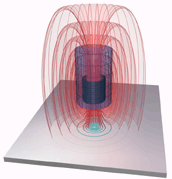
A coil is supplied
with an alternating current, which causes a magnetic field to
form around the coil. If an electrically conducting object is
placed in this magnetic field, eddy currents are induced, which
form an electromagnetic field according to Faraday's Induction
Law. This field acts against the field of the coil, which also
causes a change in the impedance of the coil. The controller
calculates the impedance by considering the change in amplitude
and phase position of the sensor coil.
The advantages
of the eddy current principle are that it can be used on all
electrically conductive, ferromagnetic and non-ferromagnetic
metals. The size of the sensor is relatively small compared to
other technologies and the temperature range is high due to the
resistance measurement of the sensor and cable. The technology
is high accuracy and is immune to dirt, dust, humidity, oil,
high pressures and dielectric materials in the measuring gap.
Restrictions
of the technology also need to be considered. Output and linearity
depend on the electric and magnetic features of the target material.
Therefore, individual linearisation and calibration is necessary.
Cable length has a maximum of 15 metres and the diameter of the
sensor (and therefore the effective measuring diameter) increases
as the measuring range increases.
The Capacitive
Principle
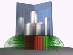
 With the capacitive
principle, sensor and target operates like an ideal parallel
plate capacitor. The two plate electrodes are formed by the sensor
and the opposing target. If an AC current with constant frequency
flows through the sensor capacitor, the amplitude of the AC voltage
on the sensor is proportional to the distance between the capacitor
electrodes. An adjustable compensating voltage is simultaneously
generated in the amplifier electronics. After demodulation of
both AC voltages, the difference is amplified and output as an
analogue signal.
Because the
sensor is constructed like a guard ring capacitor, almost ideal
linearity and sensitivity to metals is achieved. The technology
also offers high temperature stability, as changes in the conductivity
of the target have no effect on the measurement. Capacitive sensors
can also measure insulators.
However, the
technology is sensitive to changes in the dielectric sensor gap
and so is therefore ideal for clean, dry applications. Cable
length is also relatively short due to the effect of the cable
capacitance on the oscillating circuit tuning.
The Laser
Triangulation Principle
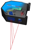
 In the laser triangulation
principle, laser diode projects a visible point of light onto
the surface of the object being measured. The back scattered
light reflected from this point is then projected onto a CCD
array by a high quality optical lens system. If the target changes
position with respect to the sensor, the movement of the reflected
light is projected on the CCD array and analysed to output the
exact position of the target. The measurements are processed
digitally in the integral controller and then converted into
a scaled output via analogue (I/U) and digital interface RS232,
RS422 or USB.
The Confocal
Principle
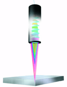
 The technology works
by focussing polychromatic white light onto the target surface
using a multi-lens optical system. The lenses are arranged in
such a way that the white light is dispersed into a monochromatic
light by controlled chromatic deviation. A certain deviation
is assigned to each wavelength by a factory calibration. Only
the wavelength that is exactly focussed on the target surface
or material is used for the measurement.
This light
reflected from the target surface is then passed via a confocal
aperture to the receiver, which detects and processes the spectral
changes. This unique measuring principle enables displacements
and distances to be measured very precisely.
Both diffuse
and spectral surfaces can be measured and with transparent materials
such as glass, a one-sided thickness measurement can be accomplished
along with the distance measurement. And, because the emitter
and receiver are arranged in one axis, shadowing is avoided.
Confocal technology
offers nanometre resolution and operates virtually independent
of the target material. A very small, constant spot is achieved
and the technology offers one-sided thickness measurement of
transparent materials. Miniature radial and axial versions of
the technology are available for measuring drilled or bored holes.
White light is used instead of a laser.
Restrictions
of the technology include the limited distance between the sensor
and target. In addition, the beam requires a clean environment.

